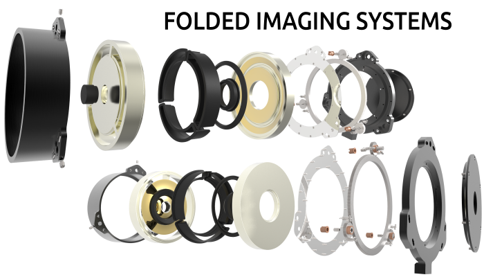
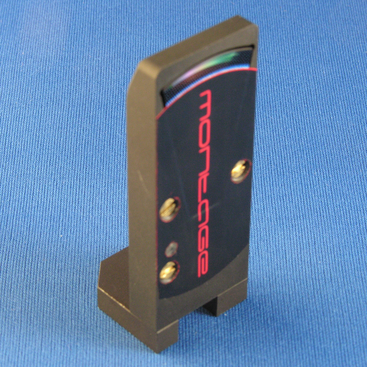
The assembled MONTAGE NANO, an 8-fold sectioned imager.
MONTAGE Phase 2 was a continuation of our work in Phase 1 and consisted of three camera systems, the Nano, the Quad, and the Quad cluster. Each system either illustrated a particular design aspect of ultra-thin cameras or improved some aspect of our Phase 1 camera.
Nano
The Nano was a sectioned version of the Phase 1 8-fold camera to improve the depth of field. Sectioning the lens into a small slice reduces the light throughput of the camera. Improving the reflector coatings and using a sensor with better wide angle pixel response allowed us to make up for most of the loss. Also, unlike the original 8-fold camera this design includes mechanical focus via the 3 adjustment scews shown in the pictures. This provides tip-tilt and z translation of the circuit board that the image sensor is mounted to resulting in a less complicated assembly process.
The Nano required a completely new circuit board assembly due to the
small form factor. However, we were able to use the same USB interface
chip in a smaller package allowing us to make use of all the software
and firmware developed in Phase 1. In addition to Phase 1 software, we
developed a Python based GUI in Phase 2 called MDOSim that interfaced
with the Nano to allow camera control and image capture. MDOSim was used
extensively in MONTAGE and in several subsequent projects.
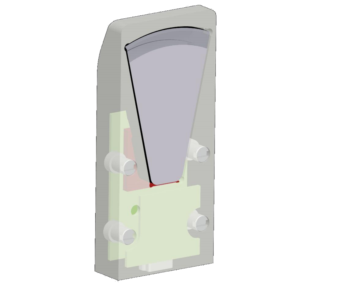
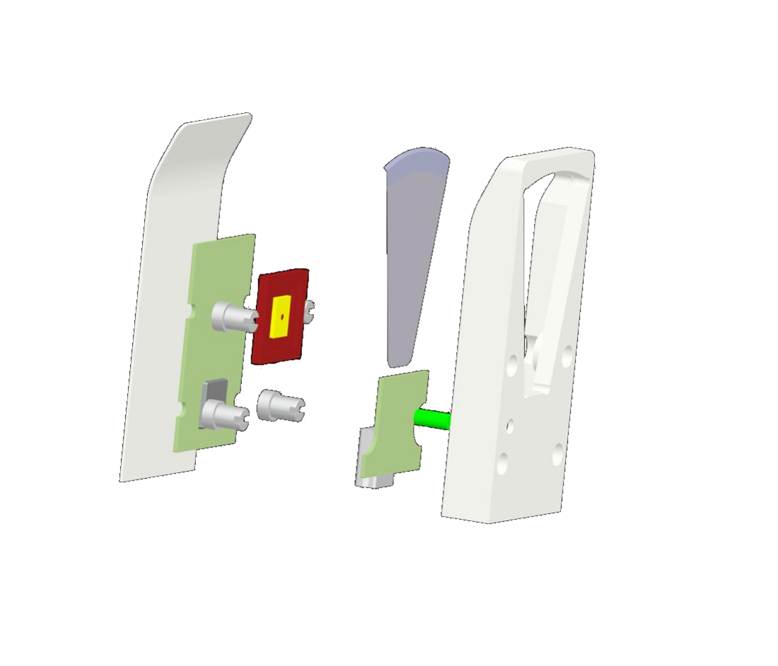
A CAD model of a sectioned 8-fold camera we call the Nano.
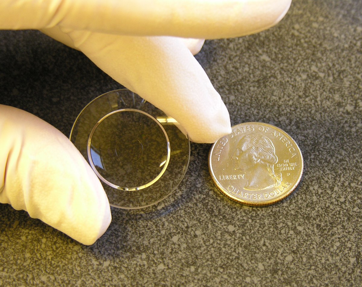
This figure shows the uncoated rear lens of the Quad next to a quarter.
Quad
The Quad camera was a completely new design and resulted from lessons learned in Phase 1. This camera is a 4-fold design but unlike the 8-fold cameras aspheric optical surfaces are on both the front and back sides of the lens. On the 8-fold design just the back surfaces had optical power and the front surface was a flat reflector. The change required that the lens was split into front and back halves to reduce the manufacturing risk. The two halves are coupled together using optical coupling gel. While this added some complexity it was also an opportunity to use the front and back separation to perform focus. Looking at the exploded view of the camera one can see that the back lens is mounted in a carriage that is positioned via a large diameter threaded focusing gear. The sensor and custom circuit board is mounted to this carriage such that it moves as a single assembly. The focusing gear is pulled up against a flat surface on the outer enclosure by four springs as shown. The optical coupling gel proved to be the biggest challenge as it did not flow easily when separating the lenses creating voids.
Like the Nano, the Quad required custom electronics. A sensor circuit board was designed with just enough circuitry to power the sensor and serialize the data for transmission to a secondary interface board. For initial testing this interface was based on our now well tested USB design requiring minimal new software development allowing for rapid development and testing.
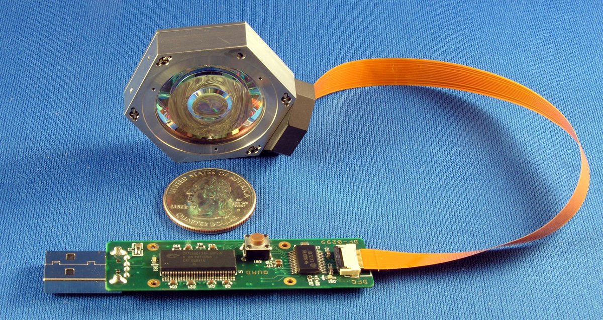
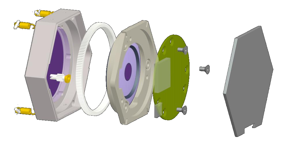
The image on the left shows the Quad camera connected to a custom USB interface. The right image is the exploded view of the Quad camera.
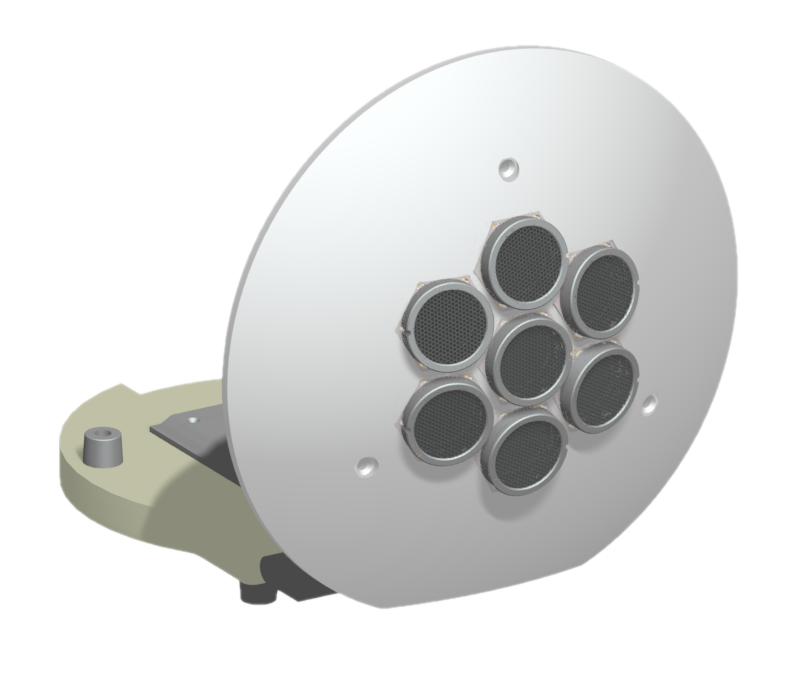
A solid model of the Quad Cluster testbed. The large base is simply to provided mechanical stability but also houses a circuit board where each Quad plugs in.
Quad Cluster
The Quad Cluster concept showed off how one might create a very thin conformal camera with a wide field of view. This was done by tiling seven Quad cameras onto a spherical surface and using custom hardware to perform real time image processing to present a seamless wide field image to the end user.
The majority of the development effort for this part of the project was focused on the "Vision Engine", a custom dual Virtex 4 FPGA board designed to receive data from 7 sensors and do real time lookup table based stitching of image date and display the final composited image on an attached DVI monitor. The user would have the ability to zoom and pan around the full image. The Vision Engine also had our standard USB interface allowing staged development of the firmware. In early testing all the data to be transfered over USB to a PC where processing was done. This allowed our algorithm and hardware teams to be working independently and provided additional flexibility for other applications.
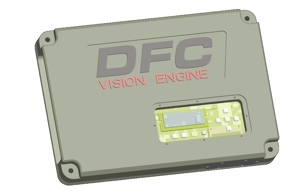
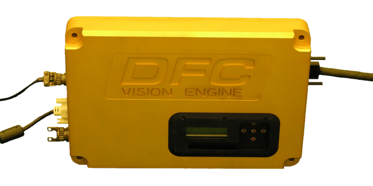
On the left is a solid model of the Vision Engine. The right image is an actual assembled unit, the enclosure is anodized Al.